
What is Brazing and Soldering?
Definition of Brazing, Soldering and Welding
According to the Metals Handbook 9th ed., welding is “a material joining process which produces coalescence of materials by heating them to suitable temperatures, with or without the application of pressure or by the application of pressure alone, and with or without the use of filler material” (Ref. (1)). From this definition, it is understandable why many people refer to brazing and soldering as welding. However, people associated with the brazing industry will argue brazing and welding are not the same. When brazing, there is no thermal melting of the joined base metals.
Brazing and soldering use filler metal with a melting point lower than the solidus point of the metal. This is the primary difference between welding and brazing. After reaching a certain temperature, generally, about 50° to 100°F higher than the melting temperature of the filler depending on the heating rate, the surface of the base metal reacts with the filler alloy to form a metallic bond. According to the American Welding Society (AWS) the only thing that differentiates soldering from brazing is temperature.
If the metal bonding process uses a filler metal that melts below 450°C (842°F) the bonding process is defined as soldering. However, if the filler metal melts above 450°C (842°F) then the bonding process is brazing (Ref. (2)). Other sources differentiate brazing from soldering in that for brazing there is a metallurgic bond created by the diffusion of the parent and filler material across the joint boundaries whereas this is not normally achieved in soldering.
Metallic Bonds
Besides metallic bonding, sometimes referred to as a metallurgical bonding, occurring during the brazing process, there are a number of other chemical processes that can occur and need to be controlled; these are: dissolution, diffusion, oxidation, the formation of intermetallic compounds (alloy), and if steels are being brazed, de-carburization.
By definition, a metallic bond is the principle bond that holds metals together and is formed between the base metal and filler metal in all welding, brazing, and soldering processes. This bond occurs as a consequence of the increased spatial extension of the valence electron wave functions when an aggregate of metal atoms are brought close together. In other words, the bond occurs because the valence electrons are shared by the metal atoms.
Diffusion
In metals, diffusion is the net movement of atoms from a region of high concentration (or high chemical potential) to a region of low concentration (or low chemical potential) resulting from the random motion of the atoms. For diffusion to occur, there is an activation energy that is necessary for atoms to jump from its lattice position to a vacancy, because the number of atoms having the necessary energy to jump goes up exponentially with temperature, the rate of diffusion goes up exponentially with temperature.
DA = Dºe -Q/RT where Da is the rate of diffusion for atom A in square centimeters per second. Dº is a constant for a given diffusion couple. e = 2.71828 the natural log base. Q is the activation energy in calories per mole. R = 1.987 cal/molºK. T is the temperature in degrees Kelvin.
While diffusion is a necessary part of brazing, typically controlling time at elevated temperatures controls diffusion and its resulting effect.
Dissolution and Oxidation
Dissolution refers to the dissolving of a solid metal into a liquid metal that is in intimate contact with it. The rate at which dissolution occurs is a function of time, temperature, and volume of liquid metal (solvent); however, temperature is the most dominant controlling factor.
Oxidation is the process of oxygen reacting with a metal to form a metal oxide, e.g. rust. All metals have a naturally occurring surface oxide layer that needs to be removed for a metallic bond during brazing/soldering. Fluxes are the most common way of reducing oxide layers and preventing oxidation of the joint area during brazing/soldering. Other methods include the use of a controlled atmosphere to prevent the creation of oxides during the brazing or soldering process.
The intermetallic compound is an intermediate phase in an alloy system having a narrow range of homogeneity and relatively simple stoichiometric proportions, in which the nature of the atomic binding can vary from metallic to ionic. Intermetallic compound layers are formed during metal-to-metal bonding as the liquid filler metal dissolves and pulls the base alloy into solution. In general, the intermetallic compound layer tends to be the most brittle part of the joint. Therefore, process variables need to be optimized and controlled to yield a strong, tough joint. Decarburization is the loss of carbon from the surface of a ferrous alloy as a result of heating in an atmosphere or medium that reacts with the carbon at the surface.
Soldering
Many different families of alloys are filler metals for soldering. However, the one thing that all soldering filler metals have in common is an alloy melting point below 450°C (842°F). These soldering alloys include lead alloys, tin alloys, and zinc alloys. Users utilize lead and tin alloys for soldering copper and brass joints. Also, lead and tin alloys utilize soldering brass to various types of coated steels. These include terneplate, tinplate, and copper/nickel clad or plated steels. Aluminum to aluminum soldering, aluminum to copper soldering, and repair of galvanized coatings all use zinc alloys.
Soldering Variables
Time, temperature, joint geometry, part alloy, type and amount of flux, type and amount of filler alloy, are the process variables that need to be controlled when soldering. These process variables control the final solder joint quality and strength. The following briefly describes how each of these variables influences the final solder joint:
- Type and amount of flux. The purpose of flux is to clean the base alloys and filler metal surfaces, keeping them from oxidizing. The type of flux affects how it reacts with the soldered metals and the temperature range. The amount of flux used has an impact on whether the solder joint forms before oxidation occurs. The consumption of the flux also influences the final time-temperature profile the joint experiences during soldering. In some instances, nitrogen, argon or other shielding gases assist the flux with preventing oxidation.
- Joint geometry. Joint geometry influences the strength of the final solder joint. It also influences if and how solder alloy pulls into the joint. Generally, a good solder joint geometry will pull filler metal into the joint and hold it in place. There is an optimum solder joint gap maximizing the strength of the solder joint. If the solder joint gap becomes too great, the joint strength dominates the bulk properties of the solder. However, if the solder joint gap becomes too tight, the strength of the joint diminishes. As a result, the solder flow pinches off during the soldering process. The joint length gives the necessary tensile and shear strength for the application. Ideally, a joint geometry that is self-fixturing is the most desirable. It does not require additional fixtures that can act as heat sinks or part restraints. These issues can lead to joint distortion and fracturing.
Part Alloys
Part alloy (substrate), filler alloy, and amount of filler alloy influence the chemical reactions occurring during the soldering process. It also influences how much dissolution occurs and what intermetallic compounds form.
For a given alloy system, time and temperature together control how much dissolution occurs. It also controls how thick the intermetallic compound layer becomes.
Temperature is the main variable controlling the speed at which the chemical reactions required to make a solder joint occur and what type of intermetallic compounds form.
Part geometry and the number of soldered joints commonly determine the heating method best suited for soldering.
Forms of Soldering
This type of soldering refers to the methods used to heat the filler metal and parts being joined by soldering. These include hot dip soldering, wave soldering, torch soldering, furnace soldering, induction soldering, iron soldering, infrared soldering, and resistance soldering. The more automated the soldering process normally the more consistent the solder joint properties are. Hand operations like torch soldering and iron soldering will have the most joint variability due to operator skill.
Soldering makes leak-free plumbing joints, electrical connections on circuit boards, joints on heat exchangers that are structural, thermally conductive, and leak-free, e.g. copper-brass radiators. Click here to read more about soldering and application practices.
Brazing
Brazing alloys are filler metals with an alloy melting point above 450°C (842°F). The most common alloy families typically used for brazing are aluminum alloys, silver alloys, copper alloys, gold alloys, and nickel alloys.
Generally aluminum braze alloys have the lowest melting ranges of the braze alloys having melting points ranging from 1040⁰ F to 1135⁰ F. The American Welding Society (AWS) refers to these alloys as BAlSi braze alloys. These are mainly aluminum and silicon.
“Hard soldering” or “silver soldering” is erroneous because silver brazing alloys melt in the range of 1145⁰ F to 1761⁰F (1761⁰F – melting point of pure silver), which is above the 842°F melting point used to distinguish between soldering and brazing. Silver braze alloys are BAg alloys, e.g. BAg-5, according to the American Welding Society (AWS).
Some of the silver brazing alloys with the lowest melting ranges (BAg-1, BAg-1a, BAg-2, BAg-2a, and BAg-3) contain cadmium, which is a toxic metal and carcinogen that gives off toxic fumes when melted. When using silver braze alloys containing cadmium, you need appropriate area venting for proper brazing performance. Because of the health hazards associated with cadmium, cadmium-free silver brazing alloys develop similar melting ranges to cadmium-bearing silver alloys.
Silver brazing utilizes the following metals: copper-copper, copper-steel, steel-steel, carbide-steel, and stainless steel-stainless steel.
Brazing Alloys
Copper brazing alloys are BCu, BCuP, or RBCuZn alloys by AWS, depending of the chemical composition of the braze alloy; but in all cases the main component of the alloy is copper. Copper-copper joints and copper-brass joints are BCuP braze alloys. The phosphorus in the alloy acts as a fluxing agent, requiring no additional flux. Users cannot use copper braze alloys that contain phosphorus with steel because of the potential to form brittle intermetallic compounds at the joint interface. Non- phosphorus copper brazing joints make up the following metals: carbide-steel, steel-steel, and stainless steel-stainless steel. The two main reasons that copper brazing alloys are used instead of silver brazing alloys are the cost of the braze alloys and melting range of the braze alloy.
Nickel Brazing Alloys
Nickel brazing alloys are BNi alloys by AWS, since nickel is the main component of these braze alloys. The melting range for nickel braze alloys range from 1610⁰F to 2111⁰F and used in aerospace, automotive, and energy. However, in certain applications nickel braze alloys, such as BNi-2, have been used for copper-copper and copper-steel joints mainly because of their melting point.
Similar to soldering, flux cleans and removes oxides from both the brazed surfaces and the braze alloy. Also, the flux protects the braze joint from oxidation while the joint forms. However as brazing temperatures go up, the number of chemical compounds that are capable of fluxing the braze joints diminish rapidly. Therefore, usually higher temperature (above 1400⁰F) commercial brazing of structures with multiple joints uses one of the following types of atmospheres: reducing, inert, or vacuum (absence of atmosphere). When brazing in a furnace, induction heating is a preheat to reduce part heating times.
Torch brazing or induction brazing have few brazed joints with localized heating with final brazed assemblies.
Torch Brazing
People use gas torches for brazing and soldering primarily because the initial capital cost is low. (Generally, one can purchase torch brazing kits for less than $2000.00, depending on the size of the torch.) However, besides the safety hazards associated with using gas torches, there are other disadvantages to using gas torches and they are as follows:
Torch Brazing Disadvantages
- High Operator skill level is required to braze with quality and repeatability with a gas
torch.- Individuals who braze with torch need to be able to select the size torch and tip for the job,
based on the thicknesses and type of the metals to be bonded. - Individuals who braze with torches need to know how to angle and move the torch around to be
able to heat the entire joint to the proper temperature without overheating the
joint or melting the base metals. - Users of gas torches need to be able to light gas torches safely and to adjust gas flow
mixtures to achieve the desired flame (carburizing, reducing, neutral or
oxidizing) for the brazing operation. - Users of gas torches need to understand how the type of fuel used effects the brazing
process.
- Individuals who braze with torch need to be able to select the size torch and tip for the job,
- Torch brazing is labor intense.
- Process variability is much larger than with other methods of brazing since no two
individuals have the exact same brazing techniques. - Bottled gases such as Butane, Propane, MAPP, or acetylene lead to with fire and explosion
hazards. These gas bottles are handled and
stored properly. - When automating with gas torches and using natural gas as the fuel gas, the heat
value of natural gas is constantly changing and this affects the process. For tightly controlled processes,
adjustments to the process have to be made as the BTU content of the natural gas changes. - With automated gas torch brazing processes tip plugging is monitored
to ensure consistency of thermal output.
However, torch brazing does work well for:
- Odd shaped joints that are not easily
heated with a specific heat pattern. - Poor fitting joints where a level of
required skill fills the joint with braze alloy.
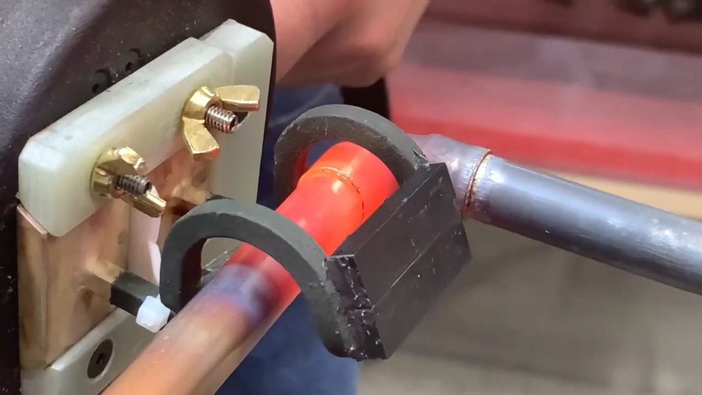
Induction Brazing
Brazing/soldering and shrink fitting are the most popular induction joining applications. Besides manufacturers looking to eliminate the burn and fire hazards associated with torches, these are reasons manufacturers utilize induction brazing:
The Importance of Utilizing Induction Brazing
- The induction brazing process uses an AC electromagnetic field to generate energy within the part. This heats the surface and sub-surface areas due to Joule effect (I2R power losses. The “I” is current density induced in the part by the electromagnetic induction field and “R” is the part’s electrical resistance). See What is Induction Heating.Therefore, you can precisely control the amount of energy put into a part, assuming the part is consistently and accurately positioned relative to the inductor, making for a very controlled brazing process.
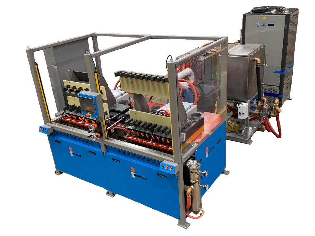
- Induction brazing lends itself to both single-piece flow (Just-in-time processing) and high volume parts brazing.
- Induction brazing is energy efficient since only the brazing process uses power. Depending on the brazed or soldered material system, as much as 80% of the input energy goes directly to the part. This is more efficient than other traditional heating processes.
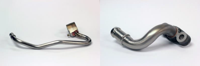
- Induction heating, when used iwith protective atmosphere chambers, allows for fluxless brazing of copper, nickel, and silver braze alloys. Typically, the only alternative to induction fluxless brazing is vacuum or other controlled atmosphere furnace brazing, which requires a significantly larger capital investment. Plus, furnace brazing cycle times are significantly longer than induction brazing cycles (minutes to hours versus seconds with induction). Figures 1 and 2 show some fluxless copper brazed automotive parts using induction heating.
Considerations with Induction
5. Induction brazing can be used for a wide variety of braze joint geometries and is not limited to simple or tubular shapes. See Figure 1 for example of some fluxless copper brazed automotive parts produced using induction heating.
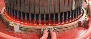
6. Induction brazing is capable of brazing large parts in a fraction of the time that can be achieved with gas torch brazing. Figure 3 shows an example of a large motor rotor being silver brazed with induction heating in less than six minutes.
In spite of all of the advantages associated with induction, there are some considerations when changing to induction heating:
- Fixturing materials- In many cases, manufacturers use mild steel brazing fixtures for torch brazing. Because induction heating uses electromagnetic energy to heat parts, changing to induction heating generally requires new non-magnetic brazing fixtures, particularly when brazing non-ferrous and non-magnetic metals. When steel fixtures are used to hold either non-ferrous or non-magnetic metals in an electromagnetic field, generally the fixture will be heated up preferentially. Therefore, induction heating braze fixtures should be non-magnetic and preferably not electrically conductive.
- Fixturing design– Another consideration is the induction braze fixturing should have minimal contact area with part being brazed to minimize the heat sink effect of the fixturing.
Inductors –
As part sizes and shapes change, inductors (coils) need to be changed to efficiently heat parts. It is the inductor shape and the gap between the inductor and part that control how the electromagnetic field couples with the part and where the joule heating occurs and ultimately the efficiency of the process.
References
Larrabee, Scott R. Eliminate Open Flames Using Induction Heating. Industrial Heating. December, 2015.